In general, the amplifier is made up of an amplifier element (transistor or tube) and auxiliary circuits for setting and stabilizing the operating point. Often, combinations of amplifiers – preamplifiers, amplifiers, power amplifiers are used in the devices. Furthermore, the article is limited to low-frequency amplifiers up to 20 kHz, which will be used mainly in audio technology.
Classification by amplifier classes
Depending on the working point (in which part of the working characteristic the amplifier works) we divide the amplifiers into so-called classes. The classes are then based on their basic involvement, advantages and disadvantages.
Class A
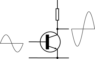 Only one amplifier element, and the working point is located in the linear part of its characteristic. Mostly in the middle, therefore, the Class A amplifier has a high linearity (small distortion) but very low efficiency (25-40%). The remaining part of the power is lost in heat. Some amplifiers allow user to change the value of the operating point (low / high volume) to optimize energy loss.
Class B
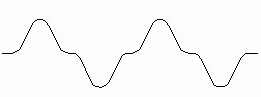
 It means two output transistors, each amplifying only the half-wave of the input signal. The wiring has a much greater efficiency compared to class A but suffers from a large transient distortion in the area where the output signal is zero. (efficiency around 75%, power is not used)
Class AB
The compromise between classes A and B is class AB, which is characterized by greater efficiency (compared to class A) and less distortion (compare to class B). Everything can easily shift the working point of both transistors so they can lead even in the amplitude range where the class B amplifier has unpleasant nonlinearities. In practice this means the activity of both transistors even in the case of small signals (class A). At higher amplitudes, one of the transistors is completely closed for part of the period. (75% efficiency, very widespread in Audi)
Class C
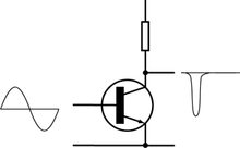 For low-frequency connection, it does not matter, but in RF technology it is good for AM and FM transmitters. The transistor is not open for half of the input signal period (base preload). The working point C moves in the active area for a much shorter time than 180 ° and is located on the “extended” conversion characteristic. The distortion is not an obstacle if the resonant circuit is in the VF collector. The amplifier requires a larger excitation signal but at the same time it works with the highest efficiency. (efficiency around 90%)
Class D

Class D amplifiers work in pulse mode similar to switching power supplies – very quickly (with a frequency much higher than the maximum transmit frequency) they switch the output between the maximum and zero voltages. The regular speaker is not enough to track fast changes, so the immediate deflection of the diaphragm depends on the off-switch and on-off times. It usually does not rely on the speaker properties, but a low pass filter is used to filter the high-frequency components. The switching signal for the output stage is obtained by pulse width modulation or delta modulation. The main advantage of the entire construction is the efficiency, which often exceeds 90%, because the output transistors are either completely closed or completely non-conductive during their operation. In this way, a situation where the transistor leads partially, when a relatively large current on it generates a large voltage drop, so that a large amount of energy has to be transformed into heat.
Class G
The G class is very similar to the AB class amplifier structures, perhaps with the difference that it is happy to use two or more power levels. If we need to process small signal levels, the amplifier selects lower power. If the amplitudes rise, the entire structure will help with a higher level of supply voltage. Class G amplifiers use less power compared to the AB class, because the maximum supply voltage will only be used when there is real need, while class AB amplifiers will run from full power continuously.
(not used)
Class H
Class H amplifiers regulate their supply voltage to minimize voltage drops in the output stage. The practical embodiment then includes a plurality of discrete levels or even a continuously adjustable size of the supply voltage. Although at first glance it may very much resemble the way that reduces class G power loss, we will not necessarily require more power supplies for Class H. This approach is more complex in comparison with other designs because it requires special structures to ensure predictability of changes and subsequent power management.
(not used)
Refferences:
https://en.wikipedia.org/wiki/Power_amplifier_classes