What kind of capacitor to choose for different construction parts in the audio? What properties apart from capacitance and limit voltage have different types of capacitors? What are the essential parasitic properties of the capacitors and which are insignificant? Does it make sense to buy overpriced branded capacitors?
In the audio field, if we limit the structure of amplifiers, speaker crossovers, and signal sources such as DAC, CD, SACD, and so on. we divided capacitors for:
Source section – power supply
Signal section – NF signal transmission
Digital part – blocking, mostly suppression
Common capacitors and their names

| Capacitor style | Dielectric | Relative Permittivity at 1 kHz |
Maximum/realized. dielectric strength V/µm |
Minimum thickness of the dielectric µm |
|---|---|---|---|---|
| Ceramic capacitors, Class 1 | paraelectric | 12–40 | < 100(?) | 1 |
| Ceramic capacitors, Class 2 | ferroelectric | 200–14,000 | < 35 | 0.5 |
| Film capacitors | Polypropylene ( PP) | 2.2 | 650/450 | 1.9 – 3.0 |
| Film capacitors | Polyethylene terephthalate, Polyester (PET) |
3.3 | 580/280 | 0.7–0.9 |
| Film capacitors | Polyphenylene sulfide (PPS) | 3.0 | 470/220 | 1.2 |
| Film capacitors | Polyethylene naphthalate (PEN) | 3.0 | 500/300 | 0.9–1.4 |
| Film capacitors | Polytetrafluoroethylene (PTFE) | 2.0 | 450(?)/250 | 5.5 |
| Paper capacitors | Paper | 3.5–5.5 | 60 | 5–10 |
| Aluminum electrolytic capacitors | Aluminium oxide Al2O3 |
9,6[7] | 710 | < 0.01 (6.3 V) < 0.8 (450 V) |
| Tantalum electrolytic capacitors | Tantalum pentoxide Ta2O5 |
26[7] | 625 | < 0.01 (6.3 V) < 0.08 (40 V) |
| Niobium electrolytic capacitors | Niobium pentoxide, Nb2O5 |
42 | 455 | < 0.01 (6.3 V) < 0.10 (40 V) |
| Supercapacitors Double-layer capacitors |
Helmholtz double-layer | – | 5000 | < 0.001 (2.7 V) |
| Vacuum capacitors | Vacuum | 1 | 40 | – |
| Air gap capacitors | Air | 1 | 3.3 | – |
| Glass capacitors | Glass | 5–10 | 450 | – |
| Mica capacitors | Mica | 5–8 | 118 | 4–50 |
Capacitor types and their basic properties
Ceramic capacitors
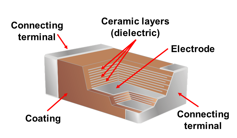 A ceramic capacitor is a non-polarized fixed capacitor made out of two or more alternating layers of ceramic and metal in which the ceramic material acts as the dielectric and the metal acts as the electrodes.
- Class 1 – ceramic capacitors with high stability and low losses compensating the influence of temperature in resonant circuit application. Common EIA/IEC code abbreviations are C0G/NP0, P2G/N150, R2G/N220, U2J/N750 etc.
- Class 2 – ceramic capacitors with high volumetric efficiency for buffer, by-pass and coupling applications Common EIA/IEC code abbreviations are: X7R/2XI, Z5U/E26, Y5V/2F4, X7S/2C1, etc.
Advantages: Very small ESR and ESL, high peak current, low temperature dependence. Excellent for RF blocking up to several GHz.
Film capacitors
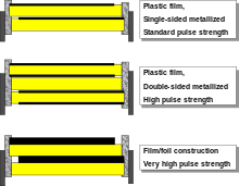 Film capacitors or plastic film capacitors are non-polarized capacitors with an insulating plastic film as the dielectric. The dielectric films are drawn to a thin layer, provided with metallic electrodes and wound into a cylindrical winding. The electrodes of film capacitors may be metallized aluminum or zinc, silver, etc., applied on one or both sides of the plastic film, resulting in metallized film capacitors or a separate metallic foil overlying the film, called film/foil capacitors.
The plastic films used as the dielectric for film capacitors are Polypropylene (PP), Polyester (PET), Polyphenylene sulfide (PPS), Polyethylene naphthalate (PEN), and Polytetrafluoroethylene or Teflon (PTFE). Polypropylene film material with a market share of something about 50% and Polyester film with something about 40% are the most used film materials. The rest of something about 10% will be used by all other materials including PPS and paper with roughly 3%
Film material, abbreviated codes
| Film characteristics | PET | PEN | PPS | PP | |
|---|---|---|---|---|---|
| Relative permittivity at 1 kHz | 3.3 | 3.0 | 3.0 | 2.2 | |
| Minimum film thickness (µm) | 0.7–0.9 | 0.9–1.4 | 1.2 | 2.4–3.0 | |
| Moisture absorption (%) | low | 0.4 | 0.05 | <0.1 | |
| Dielectric strength (V/µm) | 580 | 500 | 470 | 650 | |
| Commercial realized voltage proof (V/µm) |
280 | 300 | 220 | 400 | |
| DC voltage range (V) | 50–1,000 | 16–250 | 16–100 | 40–2,000 | |
| Capacitance range | 100 pF–22 µF | 100 pF–1 µF | 100 pF–0.47 µF | 100 pF–10 µF | |
| Application temperature range (°C) | −55 to +125 /+150 | −55 to +150 | −55 to +150 | −55 to +105 | |
| C/C0 versus temperature range (%) | ±5 | ±5 | ±1.5 | ±2.5 | |
| Dissipation factor (•10−4) | |||||
| at 1 kHz | 50–200 | 42–80 | 2–15 | 0.5–5 | |
| at 10 kHz | 110–150 | 54–150 | 2.5–25 | 2–8 | |
| at 100 kHz | 170–300 | 120–300 | 12–60 | 2–25 | |
| at 1 MHz | 200–350 | – | 18–70 | 4–40 | |
| Time constant RInsul•C (s) | at 25 °C | ≥10,000 | ≥10,000 | ≥10,000 | ≥100,000 |
| at 85 °C | 1,000 | 1,000 | 1,000 | 10,000 | |
| Dielectric absorption (%) | 0.2–0.5 | 1–1.2 | 0.05–0.1 | 0.01–0.1 | |
| Specific capacitance (nF•V/mm3) | 400 | 250 | 140 | 50 | |
A key advantage of every film capacitor’s internal construction is direct contact to the electrodes on both ends of the winding. This contact keeps all current paths very short. The design behaves like a large number of individual capacitors connected in parallel, thus reducing the internal ohmic losses (ESR) and ESL.
Some film capacitors of special shapes and styles are used as capacitors for special applications, including RFI/EMI suppression capacitors for connection to the supply mains, also known as safety capacitors, Snubber capacitors for very high surge currents, Motor run capacitors, AC capacitors for motor-run applications
Electrolytic capacitors
 Electrolytic capacitors have a metallic anode covered with an oxidized layer used as dielectric. The second electrode is a non-solid (wet) or solid electrolyte. Electrolytic capacitors are polarized. Three families are available, categorized according to their dielectric.
- Aluminum electrolytic capacitors with aluminum oxide as dielectric
- Tantalum electrolytic capacitors with tantalum pentoxide as dielectric
- Niobium electrolytic capacitors with niobium pentoxide as dielectric.
The large capacitance per unit volume of electrolytic capacitors make them valuable in relatively high-current and low-frequency electrical circuits, e.g. in power supply filters for decoupling unwanted AC components from DC power connections or as coupling capacitors in audio amplifiers, for passing or bypassing low-frequency signals and storing large amounts of energy. The relatively high capacitance value of an electrolytic capacitor combined with the very low ESR of the polymer electrolyte of polymer capacitors, especially in SMD styles, makes them a competitor to MLC chip capacitors in personal computer power supplies.
Capacitor properties
Capacitance
The capacitance of the majority of capacitors used in electronic circuits is generally several orders of magnitude smaller than the farad. The most common subunits of capacitance in use today are the microfarad (µF), nanofarad (nF), picofarad (pF)
ESR (Equivalent series resistance)

Practical capacitors and inductors as used in electric circuits are not ideal components with only capacitance or inductance. However, they can be treated, to a very good degree of approximation, as being ideal capacitors and inductors in series with a resistance; this resistance is defined as the equivalent series resistance (ESR). If not otherwise specified, the ESR is always an AC resistance[vague]measured at specified frequencies, 100 kHz for switched-mode power supply components, 120 Hz for linear power-supply components, and at the self-resonant frequency for general-application components. Audio components may report “Q factor”, incorporating ESR among other things, at 1000 Hz.
ESL (Equivalent series inductance)
Actually, the capacitor has resistance and inductance. In a simple expression, those characteristics can be written as a C, R, L serial equivalent circuit model. This R is called “Equivalent Series Resistance(ESR)”, and L is called “Equivalent Series Inductance(ESL)”. Different from an ideal capacitor, the impedance of actual capcitor changes its tendency at a certain frequency because of ESL. This frequency is called “Self Resonant Frequency(SRF)”. In higher frequency range than SRF, the impedance becomes larger by increasing frequency because ESL affects to impedance. At SRF, capacitance and ESL mutually erase each impedance. Therefore, only impedance by ESR remains at SRF.
Using the capacitors
Decoupling
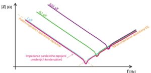
Decoupling capacitors (ceramic) are used to decoupling circuits with a wide frequency range, especially in digital parts. For these applications, more than one decoupling capacitor is needed. This can provide a low impedance at the desired frequency range to the ground on decoupling power pins. In this case, the decoupling capacitors are connected in parallel. When choosing a suitable capacitor, it is necessary to consider the selection of each of them. If multiple decoupling capacitors are used in just one case, there will be no change to the supply pin as the impedance curves of the individual capacitors will overlap.
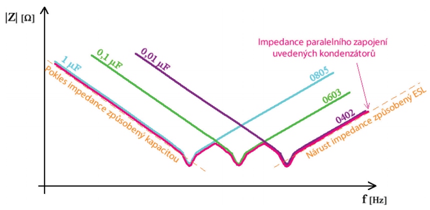 Correct use of multiple decoupling capacitors consists in selecting different bushings for these capacitors. Each case has a different frequency impedance dependence. By composing cases with others the impedance characteristic results in the resulting characteristic determined by the sum of the characteristics of the individual capacitors.
Power line filtration
The capacitors certified for permanent connection to the grid are marked X and Y with numbers.
- Class X is designed for connection between work leads (L-N, L-L). If the capacitor fails, there is a risk of a short-circuit or a fire.
- The Y-class is designed for connection between the working conductors and the conductive part of the device that can touch people (L-PE, N-PE, L-surface, N-surface). If a condenser fails, an electric shock may be present.
Coupling capacitors
In NF applications (low frequency up to 20 kHz) of amplifiers (but also VF), coupling capacitors are used in signal paths. With the capability of the coupling capacitor, the frequency component of the signal can be transferred between two different DC potentials. Very often, coupling capacitors are used in tube amplifiers and their quality has a knock-on effect on the transmitted sound.
References:
https://en.wikipedia.org/wiki/Capacitor_types
http://www.slaboproudyobzor.cz/files/20130308.pdf